Advanced Electronic Measurements Components
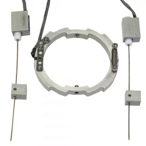
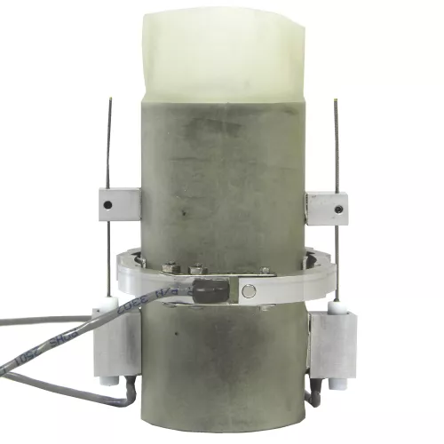
On-Sample Transducers
Used for measuring local deformation on soil sample in triaxial test.
Mini-on sample transducers hall effect
Description
In conventional triaxial testing the stiffness of a soil specimen is determined by external measurement of displacement. Such measurement are subjected to errors caused by deflections of loading system and bedding of the porous stone onto the ends of the specimen.
Local axial and radial strain transducers avoid these problems by providing the opportunity to measure the deformation, with high accuracy, directly on the triaxial test specimen.
Lacal strain transducers are supplied in a kit which includes one radial and two axial transducers suitable for 38mm, 50mm,70mm, 100mm and 150mm specimen diameters. Mounting accessories such as radial belt, mounting brackets and jig are also inclueded.
Main Features
- Suitable for specimen diameters from 38 to 150mm
- Maximum working pressure of 3400 kPa
- Light and compact construction suitable for Banded triaxial cells
- Axial and radial deformation measured directly on the triaxial test specimen
- Suitable for static and dynamic data acquisition by triaxail systems
Products
30-WF4039/KM
Mini-On sample transducer kit for 38mm dia. samples with two linear and one radial miniature transducers, radial belt, axial fixing pads and plugs. Suitable for static tests (for instance AUTOTRIAX).
30-WF4039/KN
Mini-On sample transducer kit for 38mm dia. samples with two linear and one radial miniature transducers, radial belt, axial fixing pads and plugs. Suitable for dynamic tests (for instance DYNATRIAX).
30-WF4059/KM
Mini-On sample transducer kit for 50mm dia. samples with two linear and one radial miniature transducers, radial belt, axial fixing pads and plugs. Suitable for static tests (for instance AUTOTRIAX).
30-WF4059/KN
Mini-On sample transducer kit for 50mm dia. samples with two linear and one radial miniature transducers, radial belt, axial fixing pads and plugs. Suitable for dynamic tests (for instance DYNATRIAX).
30-WF4079/KM
Mini-On sample transducer kit for 70mm dia. samples with two linear and one radial miniature transducers, radial belt, axial fixing pads and plugs. Suitable for static tests (for instance AUTOTRIAX).
30-WF4079/KN
Mini-On sample transducer kit for 70mm dia. samples with two linear and one radial miniature transducers, radial belt, axial fixing pads and plugs. Suitable for dynamic tests (for instance DYNATRIAX).
30-WF4109/KM
Mini-On sample transducer kit for 100mm dia. samples with two linear and one radial miniature transducers, radial belt, axial fixing pads and plugs. Suitable for static tests (for instance AUTOTRIAX).
30-WF4109/KN
Mini-On sample transducer kit for 100mm dia. samples with two linear and one radial miniature transducers, radial belt, axial fixing pads and plugs. Suitable for dynamic tests (for instance DYNATRIAX).
30-WF4159/KM
Mini-On sample transducer kit for 150mm dia. samples with two linear and one radial miniature transducers, radial belt, axial fixing pads and plugs. Suitable for static tests (for instance AUTOTRIAX).
30-WF4159/KN
Mini-On sample transducer kit for 150mm dia. samples with two linear and one radial miniature transducers, radial belt, axial fixing pads and plugs. Suitable for dynamic tests (for instance DYNATRIAX).
Technical Specifications
- Input voltage: 10 V
- Output voltage (ratiometric): ± 350mV (radial); ±950mV (axial)
- Accuracy (average): better than ±0.5% FRO
- Temperature coefficient: ± 0.02/FRO/°C
- Weight:
dia.(mm) radial(g) axial(g) 38 28 9 50 34 10 70 46 11 100 65 12 150 95 14
Accessories
28-WF4070/ADV
Advanced upgrading kit for triaxial cell mod. WF4070 allowing use of mini on sample transducers and bender elements.
28-WF4100/ADV
Advanced upgrading kit for triaxial cell mod. WF4100 allowing use of mini on sample transducers and bender elements.
28-WF4150/ADV
Advanced upgrading kit for triaxial cell mod. WF4150 allowing use of mini on sample transducers and bender elements.
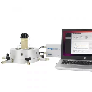
Bender Elements
Used to measure in triaxial cell the maximum shear modulus (Gmax) of soil samples
Bender elements kit with pedestal and top cap fitted to base platen of triaxial cell, master signal conditioning unit 28-WF4200 and dedicated PC software.
Description
Bender elements allow you to measure the maximum shear modulus (Gmax) of soil samples in order to evaluate their stiffness. Gmax (typically with shear strain levels of about 0.001%) is a key parameter in low-strain dynamic analysis used to predict soil behavior or soil structure interaction during earthquakes, explosion or machine and traffic vibrations.
The Bender Elements connect directly to the compact and easy-to-install smart unit comprising a signal generator and oscilloscope. Advanced user-friendly software then automates the analysis using a range of algorithms.
Bender elements test description
Bender Elements are encapsulated and mounted in inserts that are fixed into the base pedestal platen and top cap platen of a triaxial cell. They are carefully inserted into the soil specimen. When excited the bender element bends from side to side pushing the soil in a direction perpendicular to the length of the element thus having a large coupling factor with the soil.
This produces a shear wave, which propagates parallel to the length of the element into the soil sample. On the other end of the soil sample another bender element is forced to bend and produces an electrical signal that can be measured.
Theory on shear wave propagation in an elastic body tells us that the value of the shear modulus
Gmax of the soil from measurement of shear wave velocity Vs is given by:
Gmax = ρ • (Vs)2
where ρ is the mass density of the soil sample.
The system consists of a transmitter, which is energized to produce the shear waves through the soil sample, and the receiver that receive the electrical signal.
Totally new and ingenious software
According to the leading literature and research in this field, various algorithms are used to interpret wave signals:
Time difference
The Time Difference algorithm computes the wave speed and Gmax with two different methods. The first measures the wave’s flight time as a peak-to-peak difference between input and output signals. The second method measures instead the difference between the start of each signal.
Cross Correlation
The Cross Correlation measures the similarity between two signals, based on the displacement between each signal. Frequency domain analysis of cross correlation estimates the delay between input and output signals which can then be used to compute wave speed and Gmax.
Phase Angle
The Phase Angle method sees the specimen as a filter, analyzing the output signal as the filtered version of the input wave. The derivative with respect to pulsation of the phase is employed to estimate the grouped delay of the signals, allowing the computation of wave speed and Gmax
Versatile P + S wave testing system
STANDARD CONFIGURATION:
- Compact and convenient smart signal conditioning control unit comprizing a signal generator and receiver to measure S & P wave velocities with LAN PC connection (note PC is not included).
- Triaxial accessories kit for using with the Banded Triaxial Cell for compression or compression/tension test. The kit includes a base pedestal, top cap or vacuum top cap with integrated bender elements plus a pair of sintered bronze stones. ( see accessoreis)
Additional alternative bender elements configurations are available depending on users’ requirements.. Each solution still requires the signal conditioning control unit plus:
- ENCAPSULATED BENDER ONLY mounted in inserts. For use with an existing testing system.
Main Features
- HIGH PERFORMANCE: Determining S & P wave velocities enables more specimen parameters to be determined. High speed data acquisition of up to 15 Mega samples/second sample interval provides the resolution necessary for determining wave speeds
- COMPACT AND EASY-TO-INSTALL: This all-in-one turn-key system makes bender element testing easy and reliable. It conveniently includes all the necessary tools such as:Wave generator, Oscilloscope, PC software, Bender Element transmitter and receiver.
- ROBUST DESIGN: The length of the bender element inserted into the soil sample is optimized to avoid compromising the power transmitted or received by the elements. This improves resistance to breakage and makes sample preparation easier, particularly on very stiff samples where only a small recess for the element is required.
- USER-FRIENDLY GRAPHIC USER INFERFACE (GUI): The intuitive software will guide the user in automating bender element tests and quickly producing realistic estimates of shear wave travel time using a range of algorithms (Time Difference, Cross Correlation and Phase Angle). This provides maximum flexibility for waves travel interpretation in the absence of international standard methods.
- VERSATILE The system can be either added as an option to Banded Triaxial cells (upgraded with suitable kits including pedestal, top cap and porous stone); used standalone with optional accessories or as an upgrade to other manufacturers’ systems.
Products
28-WF4200
Bender element – Master signal conditioning control Unit. 230 V, 50 Hz or 110 V, 60 Hz.
Technical Specifications
- Max working pressure: 3500 kPa
- Data acquisition speed: up to 15 Mega samples/second
- Gain range for data acquisition: x5 to x1000
- Resolution of data acquisition (bits): 10
- Multi-frequency test: up to 60 kHz
- Bandwithdt: more than 100 kHz
- Multi wave generator (sine, haversine, morlet)
- Suitable for specimen with diameters ranging from 50 to 150mm (standard option only)
Accessories
28-WF4057/PS
50 mm bender elements kit – only compression – suitable for triaxial cell 28-WF4070.
28-WF4058/PS
50 mm bender elements kit – compression/extension – suitable for triaxial cell model 28-WF4070.
28-WF4077/PS
70 mm bender elements kit – only compression – suitable for triaxial cell model 28-WF4070.
28-WF4077/PS1
70 mm bender elements kit – only compression – suitable for triaxial cell model 28-WF4100.
28-WF4078/PS
70 mm bender elements kit – Compression/extension – suitable for triaxial cell model 28-WF4070.
28-WF4078/PS1
70 mm bender elements kit – compression/extension – suitable for triaxial cell model 28-WF4100.
28-WF4107/PS
100 mm bender elements kit – only compression – suitable for triaxial cell model 28-WF4100.
28-WF4108/PS
100 mm bender elements kit – compresion/extension – suitable for triaxial cell model 28-WF4100.
28-WF4157/PS
150 mm bender elements kit – only compression – suitable for triaxial cell model 28-WF4150.
28-WF4158/PS
150 mm bender elements kit – compression/extension- suitable for triaxial cell model 28-WF4150.